Sunday 10 May 2015

Highway Maintenance - Road Maintenance

Highway Maintenance - Road Maintenance

Definition / Objectives:

Preserving and keeping each type of roadway, roadside, structures as nearly as possible in its original condition as constructed or as subsequently improved and the operation of highway facilities and services to provide satisfactory and safe transportation, is called maintenance of Highways.
The various maintenance function includes;
  1. Surface maintenance
  2. Roadside and drainage maintenance
  3. Shoulder and approaches maintenance
  4. Snow and ice control
  5. Bridges maintenance
  6. Traffic service


    • Highway maintenance is closely related to the quality of construction of original road.
    • Insufficient pavement or base thickness or improper construction of these elements soon results in expensive patching or surface repair.
    • Shoulder care becomes a serious problem where narrow lanes force heavy vehicle to travel with one set of wheels off the pavement.
    • Improperly designed drainage facilities, mean erosion or deposition of material and costly cleaning operation or other corrective measures.
    • Sharp ditches and steep slopes require manual maintenance as compare to cheap maintenance of flatter ditch and soil by machine.
    • In snowy country, improper location extremely low fills and narrow cuts leave no room for snow storage, creating extremely difficult snow removal problems.

1. Surface maintenance of Roads

    • Pavement maintenance and rehabilitation programs, restore riding quality and maintain the structural integrity of the pavement over its full design life.
      Asphalt concrete pavements are subjected to various types of pavement distress or Failure these include.

i. Alligator Cracking:

    • A series of interconnecting or interlaced cracks caused by fatigue of the asphalt concrete surface under repeated traffic leading. [Cracking is due to foundation movement at subgrade]

ii. Block Cracking:

    • Cracks forming large interconnected polygon usually with sharp corners or angles. These cracks are generated by hardening or shrinking e.g. asphalt or reflection cracking for underlying layers such as cement treated base.

iii. Transverse Cracking:

    • Cracks approximately at right angle to the pavement center line. These may be caused by hardness and shrinkage of asphalt or differential thermal stresses of asphalt concrete or may be reflection cracking.

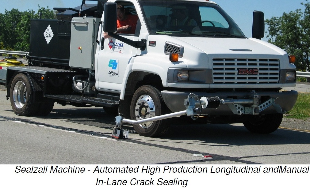
iv. Longitudinal Cracking:

    • Cracks approximately parallel to the pavement centerline. These are caused by poorly constructed construction joints and shrinkage of the asphalt concrete surface. Longitudinal Cracks in Road Highway Being SealedLongitudinal cracks may also be reflection cracks.

v. Raveling:

    • Wearing away the pavement surface caused by dislodging of aggregate particles and binders. This is usually a result of insufficient asphalt binder in the mix or stripping of asphalt from particles of aggregate.

vi. Drip Track Raveling:

    • Progressive disintegration of the surface between wheel paths caused by dripping of gasoline oil from vehicle.

vii. Bleeding or Flushing (Fatting Up):


    • The exuding of bitumen on to the pavement surface causing reduction in skid resistance. Bleeding is generally caused by excessive amount of asphalt in the mix or low air void content. It occurs in the mix in hot weather.

viii. Corrugations:

    • Due to instability of base or poor original riding surface (plastic movement of pavement)

ix. Pot Holes:

    • When cracks become deep.

x. Ruts:


    • Depressions formed under the wheel due to heavy load, this causes consolidation, deformation or plastic flow.

General surface maintenance:

        • For maintenance of gravel roads blading and occasional resurfacing is required.
        • For surface treatments of low type bituminous surface in maintenance of roads; Patching, seal coating or possible loosening oiling, re mixing and relaying are involved.
        • For high type bituminous concrete and Portland cement concrete, the Removal and replacement of failure areas and resurfacing are approximate treatment methods for highway maintenance.
        • Use same material and methods for road surface maintenance as fas as possible.
        • Highway Maintenance must be planned for rapid performance and to cause least possible disruption or hazard to traffic.

2. Roadside and Highway Drainage maintenance

    • Depends on the characters of road side where the roadside is grassy it must be mowed; cutting, ploughing or spraying with weed killer must be done.
      • If there is dry grass fire hazard burning, plowing must be done.
      • When back slope is covered with bush, trimming must be done to increase the sight distance and clearance of road.
      • Control of side slope erosion by mulching, seeding etc.
      • Picking up litter, thrown or blown along roadside or wayside area a Routine work.
      • Drainage of Highway Maintenance: Keeping ditch, culvert and other drainage structure, clean and ready to carry next flow water. Sediments deposited during period of heavy flow must be removed badly eroded channel and dikes properly protected to prevent recurrence.

3. Shoulders:

      • Depend on the surface character of these areas
        • SOD shoulders must be moved and occasionally bladed down to the level of the roadway so that water is not trapped in the traveled way. Gross must be kept in good condition.
        • Shoulders protected by bituminous blankets or surface treatments same as for roadway surface.
        • Gravel and earth shoulders that leaves a drop off at the pavement edges creates a serious accident hazard, hence, should be corrected by reconstruction, resurfacing or other appropriate means.
        • Due to continuous wetting and drying of shoulder, edge joints result between lane and shoulder which may cause settlement of pavement due to entrance of water in sub grade soil. It can Repaired by filling the joint with sand and asphalt concrete

4. Snow and ice control:

      • Ice forming on the roadway reduces coefficient of friction between tires and surface, which makes vehicle control almost impossible. In highway maintenance we can apply abrasive to heavily traveled roadway and street.
        Suitable materials that can be used are clean and sharp sand, cinders and washed stone screening.

5. Bridge maintenance:

      • Bridge Maintenance - Repainting of Exposed Steel WorkBridges maintenance is a major part of highway maintenance. Bridges can be maintained in good condition by following the below guidelines:
        • Exposed steel work must be cleaned by sand blasting flame or other means followed by repainting.
        • Deck joint may extrude or become filled with dirt so that cleaning and resealing is necessary.
        • Out of control vehicle, causing damage to guard rail, must be Repaired and strengthened.
        • If bridge deck become rough resurfacing is required
        • Remedial measures to correct serious scour around and under piers and abutments.

6. Traffic services:

      • Include stripping, sign repair and maintenance (particularly needed for repair after stormy weather.


Surface Treatment of Highways - Highway Surface Maintenance

      • Although the best type of surface course is pre-mix carpet for highway maintenance;
        1. Intensity of traffic is not very high.
        2. the pro-mix mixers are not easily available due to long transportation or technical reasons.
        3. when the cost is high.
        The surface treatment methods are employed. The surface treatment may be single or multiple.

Single Surface Treatment:

      • Is wearing course in which the bituminous material is sprayed and the aggregate is placed uniformly over the applied bitumen mineral. The thickness of such layer approximate the nominal size of aggregate used.

Multiple Surface Treatment:

      • (Double or Triple) is a wearing surface in which a course aggregate is placed on bitumen coat (prime coat) already applied, followed by spraying of bitumen and then by subsequent application of finer aggregate over a second bitumen coat. Generally the minimum size of the smallest aggregate is one of the aggregate used in the preceding application usually thickness of single layer approximately maximum size of aggregate.

Function of surface treatment:

        • to provide long lasting economical surface for granular base road having light and medium traffic volume.
        • To prevent entry of surface water into old pavement that have been weathered or cracked.
        • It improve the skid resistance of bitumen surface where the surface has polished under traffic.
        • To provide temporary cover in case of delayed incomplete pavement.
        In Highway Maintenance, For good surface treatment it is necessary that;
        • Base course is well prepared to its profile and is made more free from pot holes and ruts.
        • Excellence of surface dressing depends upon the correct proportion of binder aggregate.
        • Before laying that first surface dressing coat, the base should be made free from all dust loose soil etc.
        In all bituminous construction it is necessary that the newly surface posses a bond with the existing base at the interface. It is also necessary that the base is nearly impervious.

Highway Drainage Design | Highway Drainage Structures

Highway Drainage Design | Highway Drainage Structures

Includes collecting, transporting, and disposing of surface/subsurface water originating on or near the highway right of way or flowing in streams crossing bordering that right of way.
Drainage of highway is important because water damage highway structure in many ways. The water which are dangerous for highways are:

Rainwater: Cause erosion on surface or may seep downward and damage pavement (surface drains)
Groundwater: May rise by capillary action and damage pavement (sub-surface damage)
Water body: May cross a road (river/stream) and may damage road (cross drainage words)
It is more appropriate to take care of drainage at the time of location survey.
Ideal location fro a drainage stand point would lie along the divides b/w large drainage areas. Then all streams flow away from the highway, and the drainage problem iss reduced to caring for the water that falls on the roadway and back slope.
In contrast location paralleling large streams is far less desirable as they cross every tributary where it is largest. Ideal locations avoid steep grades and heavy cuts and fills as they create difficult problems in erosion control.

Surface Drainage of Highways - Surface runoff

Draining the roadway and road side:

Pavement and shoulder

The highway engineer should ensure that the precipitation is removed from the pavement as soon as possible and that Surface Highway Drainage on sideshighway drainage is done efficiently. Water that falls on the road way follows laterally or obliquely from it, under the influence of cross slope. Or superelevation in pavement and shoulder. A suitable value of cross fall for paved roads is about 3% for carriage way with a slope of 4-6% for shoulders. And increased cross fall for the carriage way e.g. 4%  is desirable if the quantity of the final shape of the road surface is likely to be low for any reason,


Drainage with pavement layers:


Is an essential element of structural design because the strength of the subgrade used for design purposes depends on the moisture content during the most likely adverse conditions. It is evident that benefits are derived from applying steeper cross falls to layers at successive depths in the pavement.
The top of the subbase should have a cross fall of 3-4% and the top of the subgrade should be 4-5%. These cross falls not only improve the drainage performance of the various layers, but also provide a slightly greater thickness of material at the edge of pavement where the structure is more vulnerable to damage. The design thickness should be that at the centerline of the pavement.

Road way drainage in fill:


Most common practice is to let the flow continue of the shoulder and down the  slope to the natural ground.  Little erosion,  if slopes are protected by turf or if the water flows across the roadway and down the slope as a sheet.
  • Unprotected slopes wash badly
  • Irregularities in shoulder or pavement concentrate water into small streams causing erosion e.g. at low points of sag.
  • One way of preventing washing of side slope is to retain the water at the outer edge of shoulder.

Highway drainage of run off in cut:


  • Water from traveled way and back slope is collected in road side channel, trapezoidal or triangular.
    • Design is based on slow to be accommodated.
    • Intercepting channel (sometimes called crown ditch) may be employed at the top of cut slope.

Advantages of Highway drainage in cut

      1. It prevents erosion of the back slope by runoff from the hill above.
      2. it intercepts water, not allowing it to enter side drain which may cause greater discharge in side drains

Road-way drainage in urban areas:


      1. Water falling on the road surface generally flows along the gutter to curbs or gutter inlets and from them to underground storm drains.
          • Expensive as compared to rural area drainage works.
          • We have certain justification i.e. large volume of traffic, pedestrian’s property.
          • Designed to limit the spread of water over the traveled lanes to some arbitrary maximum.
          • Inlets at low points should be designed for longer return period.

Highway runoff drainage in rural areas:


          • Generally open unlined drains with suitable x-section and longitudinal slope are provided parallel to road alignment, called longitudinal drains. In embankment they are provided on one or both side beyond the toe. In cutting area it is installed on either side of formation.
            Construction of deep open drains may be undesirable (restriction of space). In such cases covered drains or drainage trenches properly filled with layers of coarse sand and gravel may be used.

Cross Drainage Structures & Works

          • When a low laying areas or a stream or a river crosses the alignment of road, arrangements should be made to allow the water of stream or river to pass on the other side of road. The water is passed by structures known as cross drainage works. These include road culverts, bridge and cause ways.

1. Culverts:


          • Encompasses practically all closed conduits employed fro highway drainage with the exception of storm drains (covered pipes in urban area)
            • [B.S.S](a) A drain sewer or water covers totally enclosed and usually of a size through which a man can pass.
            • (b) An opening through on embankment for the conveyance of water by mean  of pipe or an enclosed channel.

2. Bridges:


            • Bridges are used in runoff drainage systems where stream span is large, for which special designs are made almost in every case > 6m.
              Common culvert types are;
              • Pipe culvert
              • Arch pipe culvert
              • Box culvert
              • Bridge culvert
              • Arch culvert

3. Cut off walls:


              • Extending below the level of expected scour.
                • Culverts are usually installed in the original stream bed with their grades confirming to those of natural channel. In this way distribution to stream flow and the erosion problem it create are held to minimum.

4. Dips or cause ways in Highway Drainage:


              • A dip is formed by lowering the roadway grade to the level of the stream from the bank to bank of the stream. Vertical curves at each end transition back to the regular grade line. Washing of the roadway surface is prevented by curtain wall of concrete rubble masonry. With proper design it is damaged little by flood water, so that maintenance cost are low. With long transition at ends they ride smoothly.
                Disadvantage of dips is interruptions and hazard to traffic when the dip is flowing.

5. A dip culvert combined:


              • (High level causeway) has been sometime employed to grade advantage. Partially lowered pipe culverts under the road surface at stream bed level carry small flows without inconvenience to traffic. The larger waterway capacity of the dip comes into play during major floods.

Sub Surface Highway Drainage

                • Subgrade may be damaged by sub soil water.
                • Sub soil water as free water, when water table is high or it may come up by capillary action to the subgrade when water table is low.
                • Subgrade should be of self draining material so that it may pass off the percolation water that comes to it to remain dry and stable.
                • But if subgrade is of soft and retentive soil, or there are underground dprings bringing free water to the subgrade fro that reason subsurface drains should be constructed about 1 ½’ to 2’ below the formation level to carry away water from the subgrade and thus keep it dry. ( in easily drainable soil water can be lowered by deep or open side drains, it also takes rain water.
                • Cross-drains may be in the form of trapezoidal trenches filled with selected rubble called rubbled drains or trench drains.
                • Depth is not much and the discharge is small.
                • The pipes are surrounded by filler material and the remaining of the cross trench is filled with graded rubble,  the bigger size rubble being nearer to the pipe. Water of wet subgrade passes through the open joint of pipes and enter the lateral drain which discharge into the longitudinal drain pipe in the two longitudinal side trenches.
                • Longitudinal drain carry water to the nearby stream.
                • Cross-drains, staggered in herring bone fashion.
                • Spacing of lateral drains is less in impermeable soil and more in permeable soil.

Intercepting drains:


                • For control of seepage in cuts or side hill locations.
                  Highway Drainage of runoff water


Marshall Stability Test - ASTM D6927 - 06 Standard

Marshall Stability Test - ASTM D6927 - 06 Standard

Marshal Test

Marshal test is extensively used in routine test programs for the paving jobs. The stability of the mix is defined as a maximum load carried by a compacted specimen at a standard test temperature of 600 °C. The flow is measured as the deformation in units of 0.25 mm between no load and maximum load carried by the specimen during stability test (flow value may also be measured by deformation units of 0.1 mm). This test attempts to get the optimum binder content for the aggregate mix type and traffic intensity. This is the test which helps us to draw Marshall Stability vs. % bitumen.

Test Procedure of ASTM D6927 -06 Standard Test:

The apparatus for the Marshall Stability test consists of the following:
  1. Specimen mould assembly comprising mould cylinders 10.16 cm diameter by 6.35 cm height, base plate and extension collars.
  2. Specimen extractor for extracting the compacted specimen from the mold. A suitable bar is required to transfer load from the extension collar to the upper proving ring attachment while extracting the specimen.
  3. Compaction hammer having a flat circular tamping face 4.5 kg sliding weight constructed to provide a free fall of 45 cm.
  4. Compaction pedestal consisting of a 20 × 20 × 45 cm wooden block capped with 30 × 30 × 2.5 cm MS plate to hold the mould assembly in position during compaction. Mold holder is provided consisting of spring tension device designed to hold compaction mould in place on compaction pedestal.
  5. Breaking head: this consists of upper and lower cylindrical segments or test heads having a inside radius curvature of 5 cm. the longer segment is mounted on a base having two perpendicular guide rods which facilitate insertion in the holes of upper test segment.

Loading Machine:

  1. It is provided with a gear system to lift the upward direction. Pre-calibrated proving ring of 5 tones capacity is fixed on the upper end of the machine, specimen contained in the test head is placed in between the base and the proving ring. The load jack produces a uniform vertical moment of 5 cm per minute. Machine is capable of reversing its moment downward also. This facilitates adequate space for placing test head system after one specimen has been tested.
    Flow meter consists of guide, sieve and gauge. The activating pin of the gauge slides inside the guide sleeve with a slight amount of frictional resistance. Least count of 0.025 mm is adequate. The flow value refers to the total vertical upward movement from the initial position at zero loads to value at maximum load. The dial gauge of the flow meter should be able to measure accurately the total vertical moment upward.
    Marshal Stability test Loading Apparatus
    In addition to above the following general equipment are also required:
    1. Oven or hot plate
    2. Water bath
    3. Thermometers of range up to 200 °C with sensitivity of 2.5 °C and Miscellaneous equipment like containers, mixing and handling tools etc.

Preparation of Test Specimen

      1. 1200 grams of aggregate blended in the desired proportions is measured and heated in the oven to the mixing temperature.
      2. Bitumen is added at the mixing temperature to produce viscosity of 170 ± centi-stokes at various percentages.
      3. The materials are mixed in a heated pan with heated mixing tools.
      4. The mixture is returned to the oven and reheated to the compacting temperature (to produce viscosity of 280±30 centi-stokes).
      5. The mixture is then placed in a heated Marshall mould with a collar and base and the mixture is spaded around the sides of the mould. A filter paper is placed under the sample and on top of the sample.
      6. The mould is placed in the Marshall Compaction pedestal.
      7. The material is compacted with 50 blows of the hammer (or as specified), and the sample is inverted and compacted in the the other face with same number of blows.
      8. After compaction, the mold is inverted. With collar on the bottom, the base is removed and the sample is extracted by pushing it out the extractor.
      9. The sample is allowed to stand for the few hours to cool.
      10. The mass of the sample in air and when submerged is used to measure the density of specimen, so as to allow, calculation of the void properties.

Marshal Test Procedure

        1. Specimens are heated to 60 ± 1 °C either in a water bath for 30 - 40 minutes or in an oven for minimum of 2 hours.
        2. The specimens are removed from the water bath or oven and place in lower segment of the breaking head. The upper segment of the breaking head of the specimen is placed in position and the complete assembly is placed in position on the testing machine.
        3. The flow meter is placed over one of the post and is adjusted to read zero.
        4. Load is applied at a rate of 50 mm per minute until the maximum load reading is obtained.
        5. The maximum load reading in Newton is observed. At the same instant the flow as recorded on the flow meter in units of mm was also noted.


Road Construction Machinery

Road Construction Machinery

Road construction equipments are found in a wide variety ranging from the very heavy equipment to portable and lighter equipment. These modern and high construction equipments make the construction job easier and quicker.
Also the work done my heavy machinery is of good quality, this is the reason that we find a wide variety of equipments at every construction site. The heavy machines make possible a lot of tasks to be completed safely and more reliably that cannot be carried out manually. However, the equipment always requires a person or two to perform its heavy functions. The construction work carried out by the manifold heavy equipments can be classified into three major categories which are as follows:
  1. Earthwork Machinery
  2. Road Works Machinery
  3. Lifting Machinery

Earthwork Machinery:

  1. Construction MachineryThis involves the engineering works where large quantities of materials such as soils or rocks are needed to be transferred from the origin to the site where the road is being constructed. The construction machines used to carry out the earthen works include excavators, loaders, dozers, graders and scrapers

Excavators:

  1. As the name indicates excavators are used to dig the earth. They are quite commonly used in construction and are an essential part of the resources that are required for any building project.

Loaders:

  1. They are also used for digging and are universally considered to perform faster than the excavators. Their main function is to move loose soil

Dozers:

  1. The dozer machines are used to prepare the surface to be constructed by moving and changing the soil. A dozer is a useful machine which pushes and spreads the soil to create a flat and even surface.

Graders:

  1. The function of a grader is quite similar to the dozer. It is used to smooth out the construction surface and level it. This equipment is particularly useful in road construction sites.

Scrapers:

  1. Scraper is another type of construction equipment which is used to scrap a thin layer of soil and then carry it meters away as desired. They are commonly used in big project sites.

Road Work Machinery:

  1. All the functions involved in the construction of roads fall under this category. Road construction is a common application of the construction equipments.

Milling Machine:

  1. The milling machine in road works is used for repair works to remove a layer of unwanted material from roads so that a new layer can be created by disposing off the destroyed layer.

Paver:

  1. A paver is an essential road construction machine used to lay out or spread asphalt or concrete layer on roadways.

Compactor:

  1. Compactors are used for compacting the various layers of the roads after spreading them. As the name indicates compactors as a road construction machines are used to compress the materials in construction sites and roads. They compress and compact the soil for further construction purpose or compact the asphalt or concrete roads in a smooth layer enabling them to function properly.

Lifting Machinery:

  1. These equipments are used to lift the heavy objects and materials on the construction sites. They occur in varying types depending on the requirement or height of lifting and the object to be lifted.

Tower Crane:

  1. They are used to lift different building materials such as concrete, steel etc and they have the specific function of rising to a great height.

Tractor Crane:

  1. They are also used for lifting and carrying heavy materials on the construction site and they can move about freely because of their compact structure.

    Truck-Mounted Crane:

  1. These cranes are most widely used because of the advantage that they can move easily on the roads. They are used for short duration projects.

Typical Road Structure Cross Section - Road Cross Section Details

Typical Road Structure Cross Section - Road Cross Section Details


Composition of structure:
Road Structure Cross Section is composed of the following components
  1. Sub Base
  2. Base Course
  3. Sub Grade
  4. Surface/Wearing Course

1. Sub Bases:

  • It is layer of granular material provided above subgrade generally natural gravel. It is usually not provided on subgrade of good quality.

    a. Function of Sub base in Road Cross Section

    • It enables traffic stresses to be reduced to acceptable levels in subgrade in the Road Structure Cross SectionRoad Cross Section.
    • It acts as a working plate form for the construction of upper pavement layers.
    • Acts as a drainage layer, by protecting the subgrade from wetting up.
    • It intercept upward movement of water by capillary action.
  • It acts as a separating layer b/w subgrade and road base. By this it prevent the two layers from mixing up.

  • b. Characteristics of materials used in Sub Base:


    The subgrade material should be clean and free from organic matter and should be able to be compacted by roller, to form stable sub-base. The material should have following characteristic.

    • Well graded uniformity coefficient (D60/D10) should not be less than 3.
    • Fraction passing sieve #200 shall not be greater than 2/3rd of the fraction passing sieve #40.
    • Should have a L.L not greater than 25%.
    • P.I not greater than 6
    • CBR should not be less than 25. Arrow See also: CBR Test Procedure
    • In coarse grain, aggregate retained by #10 sieve, %age of wear shall not be greater than 5%.
    • The max dia of any particle shall not be greater than 2/3ed of the layer thickness of sub-base.
    • Typical particle size distribution for the sub-base (granular) when will meet strength requirement are

    • B.S Sieve Size% By mass of total Aggr passing test sieve
      50100
      37.580-100
      2060-100
      530-100
      1.15170-75
      0.39-50
      00755-25

      * To avoid intrusion of silt and clay material in sub-base from subgrade
      D15 (sub base) < 5
      D15 (sub grade)
      • Recommended plasticity characteristic for granular Sub Base (Road Note 31) are;

        ClimateLiquid Limit (L.L)Plasticity Index (P.I)
        Moist or wet tropical< 35< 6
        Seasonal wet tropical< 45< 12
        Arid & Semi Arid< 55< 20
  • 2. Sub Grade in Road Structure Cross Section:

    3. Base courses in Road Structure Cross Section

    • It is the layer immediately under the wearig surface (Applies whether the wearing surface is bituminous or cement concrete and or more inch thick or is but a thin bituminous layer).
    • As base course lies close under the pavement surface it is subjected to severe loading. The material in a base course must be of extremely high quality and its construction must be done carefully.

    a. Types of Base Course

    1. Granular Base Course:

    A mixture of soil particles ranging in size from coarse to fine. Processing involve crushing oversized particles and screening where it is necessary to secure the desired grading. The requirements of a satisfactory soil aggregate surface are;
    • Stability
    • Resistance to abrasion
    • Resistance to penetration of water
    • Capillary properties to replace moisture lost by surface evaporation upon the addition of wearing course requirement change.

    2. Macadam Base:

      Successive layers of crushed rock mechanically locked by rolling and bonded by stone screening (rock duct, stone chips etc).

    3. In-water bound Macadam:

    The crushed stones are laid, shaped and compacted and then finer materials are added and washed into surface to provide a dense material.

    4. Treated Bases:

    Compose of mineral aggregate and additive to make them strong or more resistant to moisture. Among the treating agents is bitumen.

    4. Surface/Wearing Course in pavement cross section:

    The top layers of pavement which is in direct contact with the wheel of the vehicle. Usually constructed of material in which bitumen is used as binder materials.

    a. Bituminous Pavement:

    Consists of combination of mineral aggregate with bituminous binder ranging from inexpensive surface treatment ¼ in or less thick to asphaltic concrete.
    For good service throughout the full life bituminous pavement must retain following qualities.
    • Freedom from cracking or raveling.
    • Resistance to weather including the effect of surface water heat and cold.
    • Resistance to internal moisture, particularly to water vapors.
    • Tight impermeable surface or porous surface (if either is needed for contained stability of underlying base or subgrade).
    • Smooth riding and non skidding surface.

    The design should be done so that to meet the above requirements for considerable number of years (need proper design and construction supervision)
    Pavement meeting all the requirements above have been product if six distinctly different construction processes as follows.
    • Heat a viscous bituminous binder to make it fluid, then in a plant mix it with heated aggregate place and compact the mixture while it is hot.
    • Use fluid bituminous binder, mix it with aggregate at normal temperature. Mixing may be done at a plant (plant mix) or on the prepared roadway base (road mix). Spread and compact the mixture at normal temperature.
    • Add solvent such as naphtha or kerosene to a viscose bituminous binder to make it fluid with aggregate at normal temperature by either plant or road mix methods. Spread and compact at normal temperature before solvent evaporates.
    • Use fluid emulsion of viscose bituminous binder in water, mix it with aggregate at normal temperature by either plant or road mix method. Spread and compact at normal temperature before the emulsion breaks down with its components.
    • Spread and compact clean crushed aggregate as for water bound macadam. Over it spray heated dissolved or emulsified bituminous binder which penetrates open areas of the rock and binds the aggregate together. Thus is commonly called “Penetration Method”.
    • Spread bituminous binder over the roadway surface then cover it with properly selected aggregate. This is commonly called the “Inverted Penetration Method”.
    Selections based on the requirements and economy, large volume of heavy vehicles, low traffic volume etc.

Typical Road Structure Cross Section - Road Cross Section Details

Typical Road Structure Cross Section - Road Cross Section Details


Saturday 9 May 2015

Typical Cross Section of a Highway

Roadway Cross Section | Typical Highway Cross Section 


The typical cross section provided by AASHTO for a two lane highway is given below.


Highway Cross Section Elements

1. LANE WIDTH OR HIGHWAY TRAVEL WAY:


In meeting oncoming vehicle or passing slower ones, the portion selected by a driver depends primarily on the paved surfaced width of the highway. The width of the surfaced road and the no of lanes sho7uld are adequate to accommodate the type and volume of traffic anticipated and the assumed design speed of vehicles.
As traffic density, vehicle speed and truck widths have increased, two lane highway have also increased in width from 16’ to the current recommended value of 24’ width 10; stabilized or paved shoulders on either side along primary routes.
Standard for the interstate system set lane width at 11’ for rural roads when traffic density is less than 200 vehicles per lane per hour.
For other rural and all urban facilities widths are set to be 22’. For primary highway carrying over 200 vehicles, lane widths are 11’ per 12’ depending on design speed and no of commercial vehicles.
For secondary roads desirable lane is 10’.

2. MEDIAN SRIP FOR DIVIDED HIGHWAY:-


In order to provide positive protection against a conflict with opposing traffic median strop are provided on divided highways.
The width of these median strip varies from 4’ to 60’.
Where median strips are narrow separation, is merely provided by raised curbs and, where greater widths are available curbs may (or may not) be used. Often in rural areas the wide division aline serves the purpose and no raised barrier is employed.

ADVANTAGES of Median of a road

Are given as;
  1. The chance of freak accidents which might produce head on collision over a narrow median is reduced.
  2. Headlights glare from opposing traffic is less troublesome.
  3. At intersection, a wide median provides refuge from crossing traffic.
Due to high cost of land, narrow width is provided at normal sections and added widths where right turn or x-traffic are to be accommodate are used.
Medians are often narrowed at grade separation in order to reduce the length or width of the structure.
Median width of 60’ or wide are inadvisable at signalized intersection locations because extra time is required.
WIDTH - (INTERSTATE)
RuralUrban
40’
12’
15’
4’
Desirable Minimum

3. SHOULDERS in Highway Cross Section :


It is that portion of the roadway between the outer edge of the outer traffic lane and the inside edge of the ditch, gutter, curb or slope.
Shoulders are provided for the safe operation and to allow the development of full traffic capacity. Shoulder provides a place for vehicle to park for changing tires.
DIMENSIONS:
  1. Outside shoulders are width of at least 10’ and preferably, 12’ that is clear of all obstructions is desirable for all heavily traveled and high speed highways.
  2. Inside shoulder are often not as wide (often 4’)
  3. Mountainous areas: due to extra cost, the width is kept less, the use of partial shoulder may be permitted (protrude 1’-4’ into adjacent lane) under these conditions, emergency parking pull outs are provided.
  4. In section with guardrails or other vertical elements, an additional 2’ of shoulder widening should be provided.
It is common to pave it inside from 18” to 3’ with bituminous material or at least to apply bituminous surface treatment. In some instances, full width is paved or treated. Turfed shoulders are provided in areas with sufficient rainfall. It is common practice to mark the line between roadway and shoulder as guide.
Slope of the shoulder should be greater than that of pavement shoulder with high type surface. Slope form 2 to 6%, gravel 4 to 6% and turf 6 to 8% to assure efficient drainage away from pavements.
  • One argument for wide, continuous shoulder is that they add structural strength to the pavement.
  • Outside shoulder increase horizontal sight distance on curve.


    4. SIDE SLOPES in Roadway Cross Section:


    The graded area immediately adjacent to the graded roadway shoulder is called side slope

    Highway Cross Section - Types of Side slopes:

    BACKSLOPE: - Slopes back to natural topography are known as back slope.
    FARESLOPE: - Slopes down to ditch are called fare slope.


Geometric design of highways

Geometric design of highways

Learning Objectives

To understand the considerations and quantifiable aspects of geometric design consider
  1. Locational Design
  2. Current land use
  3. Geology
  4. Future land use
  5. Existing infrastructure

Controls and Criteria

  • Design Vehicles
    • Passenger cars, buses, trucks, RVs
    • Physical characteristics: weight, dimensions
    • Establish intersection radius, pavement markings
  • Vehicle Performance
    • Operating characteristics: accel/decel
    • Impacts air quality, noise, land use


      Driver

      • Information handling
      • Reaction timeDriver Errors Graph Statistics
        • Time to perceive + react to a hazard in vehicle’s path
        • Expected/unexpected
      • Speed
      • Driver errors
      • Traffic
      • Composition and volume
        • Average daily traffic (ADT) is not adequate
        • Design hourly volume (DHV)
        • 30th-highest hourly volume (30HV) in one year
        • K-factor (% of ADT; 8~12% urban, 12~18% rural)
      • Speed of the vehicles
        • Operating Speed (typically the 85th percentile speed)
        • Free-flow Speed (close to zero density)
        • Running Speed (actual speed)
        • Design Speed (as high as practical)
      • Capacity
        • Maximum hourly flow rate (per lane) under prevailing conditions
        • Determines adequacy of existing roadways
        • Helps select roadway type
        • Helps define needs
        • Design level of service (LOS)


          Capacity Variance by Free Flow


          Stopping and Sight distance

          Length of roadway that should be visible ahead of you in order to ensure that you will be able to stop if there is an object in your path.
          Calculate the SSD for a vehicle traveling on your roadway at the design speed, and then make sure the actual sight distance that you provide is at least as great as the stopping sight distance
          • Assume
            • Driver eye height of 3.6 feet
            • Height of object between 2.0 and 3.6 feet
          • Reaction distance + braking distance


            Braking Distance Reaction
            • Design standard: tr=2.5, a=11.2


              OtheR sight distances

              • Decision sight distance
                • Allow longer tr for information processing for different maneuver conditions (table 6-5)
              • Passing sight distanceOther Sight Distance
                • Ensure safe passing maneuver (figure 6-5)
                • 4 distance components (figure 6-6)
              • At 70 mph
                • SSD = 730 ft
                • DSD = 1445 ft (maneuver E)
                • PSD = 2480 ft

              Horizontal Alignment

              Basic controlling expression

              Horizontal Alignment Formula
              e = rate of superelevation
              u = side friction factor (dep. on pavement, speed, …)
              V = vehicle speed
              R = radius of
              curve
            • Overall design procedure

              • Determine a reasonable maximum superelevation rate.
              • Decide upon a maximum side-friction factor.
              • Calculate the minimum radius.
              • Iterate and test several different radii until you are satisfied with your design.
              • Make sure that the stopping sight distance is provided.
              • Adjust your design if necessary.
              • Design the transition segments.


              • Super Elevation of roadsSuper Elevation

                • Tilting the roadway to help offset centripetal forces developed as the vehicle goes around a curve
                • General Practice

                  • Highways, no ice/snow
                    emax = 0.10
                  • Highways, snow/ice 
                    emax = 0.06
                  • Traffic congestion or roadside development, limit speeds
                    emax = 0.04 ~ 0.06


                  • Side Friction

                    Design based on point where centrifugal force creates feeling of discomfort for driver
                    Speedu maxu design
                    200.500.17
                    300.350.16
                    400.320.15
                    500.300.14
                    600.290.12
                    700.280.10