Saturday, 9 May 2015

Geometric design of highways

Geometric design of highways

Learning Objectives

To understand the considerations and quantifiable aspects of geometric design consider
  1. Locational Design
  2. Current land use
  3. Geology
  4. Future land use
  5. Existing infrastructure

Controls and Criteria

  • Design Vehicles
    • Passenger cars, buses, trucks, RVs
    • Physical characteristics: weight, dimensions
    • Establish intersection radius, pavement markings
  • Vehicle Performance
    • Operating characteristics: accel/decel
    • Impacts air quality, noise, land use


      Driver

      • Information handling
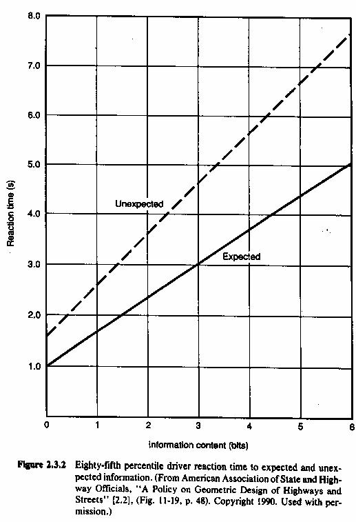
      • Reaction timeDriver Errors Graph Statistics
        • Time to perceive + react to a hazard in vehicle’s path
        • Expected/unexpected
      • Speed
      • Driver errors
      • Traffic
      • Composition and volume
        • Average daily traffic (ADT) is not adequate
        • Design hourly volume (DHV)
        • 30th-highest hourly volume (30HV) in one year
        • K-factor (% of ADT; 8~12% urban, 12~18% rural)
      • Speed of the vehicles
        • Operating Speed (typically the 85th percentile speed)
        • Free-flow Speed (close to zero density)
        • Running Speed (actual speed)
        • Design Speed (as high as practical)
      • Capacity
        • Maximum hourly flow rate (per lane) under prevailing conditions
        • Determines adequacy of existing roadways
        • Helps select roadway type
        • Helps define needs
        • Design level of service (LOS)


          Capacity Variance by Free Flow


          Stopping and Sight distance

          Length of roadway that should be visible ahead of you in order to ensure that you will be able to stop if there is an object in your path.
          Calculate the SSD for a vehicle traveling on your roadway at the design speed, and then make sure the actual sight distance that you provide is at least as great as the stopping sight distance
          • Assume
            • Driver eye height of 3.6 feet
            • Height of object between 2.0 and 3.6 feet
          • Reaction distance + braking distance


            Braking Distance Reaction
            • Design standard: tr=2.5, a=11.2


              OtheR sight distances

              • Decision sight distance
                • Allow longer tr for information processing for different maneuver conditions (table 6-5)
              • Passing sight distanceOther Sight Distance
                • Ensure safe passing maneuver (figure 6-5)
                • 4 distance components (figure 6-6)
              • At 70 mph
                • SSD = 730 ft
                • DSD = 1445 ft (maneuver E)
                • PSD = 2480 ft

              Horizontal Alignment

              Basic controlling expression

              Horizontal Alignment Formula
              e = rate of superelevation
              u = side friction factor (dep. on pavement, speed, …)
              V = vehicle speed
              R = radius of
              curve
            • Overall design procedure

              • Determine a reasonable maximum superelevation rate.
              • Decide upon a maximum side-friction factor.
              • Calculate the minimum radius.
              • Iterate and test several different radii until you are satisfied with your design.
              • Make sure that the stopping sight distance is provided.
              • Adjust your design if necessary.
              • Design the transition segments.


              • Super Elevation of roadsSuper Elevation

                • Tilting the roadway to help offset centripetal forces developed as the vehicle goes around a curve
                • General Practice

                  • Highways, no ice/snow
                    emax = 0.10
                  • Highways, snow/ice 
                    emax = 0.06
                  • Traffic congestion or roadside development, limit speeds
                    emax = 0.04 ~ 0.06


                  • Side Friction

                    Design based on point where centrifugal force creates feeling of discomfort for driver
                    Speedu maxu design
                    200.500.17
                    300.350.16
                    400.320.15
                    500.300.14
                    600.290.12
                    700.280.10

Factors affecting Selection of Highway location in urban

Factors affecting Highway location in urban areas

In general, the sequence of highway location in the urban areas is the same as in rural area i.e. reconnaissancepreliminary location andfinal location. The location is chiefly dictated by the desired and points of travel, topography, geology and environmental impact.
For urban highways location process, however, is more involved reflecting the complexities of urban conditions.
Among factors that affect selection of highway location are:
  1. Traffic/Trip orientation and purpose.
  2. Land use
  3. Off-street parking
  4. Other transportation system
  5. Topography and geology
  6. Sociological conditions
  7. Historical and environmental impacts.

1. TRAFFIC / TRIP ORIENTATION AND PURPOSE


  1. Traffic planner from various studies can predict the effect of travel patterns of alternative location proposed highway. Also they analyze the probable effect of new links in highway network.
    This permits the location engineer to determine how well alternative locations will fit with the existing network.

2. LAND USE


  1. It is a major factor affecting the pattern of traffic generation is an urban areas. For urban highway the commercial, residential and industrial areas are too considered.
    Although the highway should be designed for peak hour volume and the travel patterns vary with time of day, day of weak. Season of the year also has effect in other ways.
    Industries and common areas relying heavily on truck transportation need service by arterial routes. Health and safety require avoiding heavy traffic in residential areas. Aesthetic values are also considered in an urban highway.

3. Parking Facility for Vehicles


  1. For highway location in an urban area the existing parking facility should be considered. Ideally the location should be close to existing and potential parking areas to avoiding the amount of travel on existing street.

4. Already existing Transportation System


  1. To increase the overall level of service of transportation in an urban area interference and interaction with other transportation system should be considered.

5. Topography and Geology


  1. Same importance as in rural area. Due to high cost of right of way are certain areas from where the road should not pass.

6. Sociological, Historical and Environmental factors


    • Proposed location should not serve residential neighborhoods or create barriers b/w residential and other community service.
    • Open public land should be retained as far as possible.
    • Park an residential land should be used only if there is no alternate location can serve as stabilizing force by screening the traffic from residential communities.
    • Further relocation of utilities where depressed highway and under pass are involved can add greatly to the cost.
    • The procedure for locating urban highway are much less uniform and fixed e.g. there may be prior surveys and maps made for property location, street improvement or other purposes which furnish most of the information that will be gathered by reconnaissance. In many instance the data may be complete and accurate enough that no preliminary survey is required.
    • Aerial photographs, the primary reconnaissance too, avoid highly developed areas of high cost.
    • Just as in rural areas, location survey consists of staking and referencing the centerline, taking profile, and cross-sections, and determining the location of all cultural and property movements.
    • Considerable time is needed for locating surface and underground utilities, so that construction plans can include provision for their location.
    • Problems can be minimized by employing large scale vertical aerial photographs and maps made from the photographs by photogrammetric survey.


Location Surveys for Highway

Location Surveys for Highway


The aim of location survey is to select a route with the following points kept in mind.
  1. With reasonable economy it should meet the minimum requirement regarding curvature and grades.
  2. To produce an easy riding (traveling), free flowing traffic artery that has a high capacity and it meets all the safety standards.
  3. The location survey should recognize and evaluate the routes impact on already existing industries, business, and residential values and on future development.
Before field survey for any highway location is started, tentative decision, regarding the design speed of the route, its cross-section, and the maximum grade must be made. These decision made are based on the;
  • Estimated of amount, character and hourly distribution of traffic, along with
  • Knowledge of the area is traversed.
  • And available funds.


    RESULTING ROUTE: After comparison of the different alternative design, the route is selected which has cheapest overall cost, considering capital investment, maintenance, expense and saving to the road user.

THE RURAL HIGHWAY LOCATION AND DESIGN PROCESS

  • The rural highway location and design process is elaborated in a flow chart given below (which are then discussed one by one.)

    The possible desk study for highway of an area include;
    Maps, Aerial photographs, charts or graphs to obtains, engineering data, environmental data, social data, economic data.

ENGINEERING DATA:

  • All details of the topography , soil and problems like drainage and maintenance, should be investigated before a scientific plan programmed can be suggested. The engineering data includes following things;
    1. Topographic and geological maps.
    2. Stream and drainage basin maps.
    3. Climatic records.
    4. Preliminary survey maps of previous projects.
    5. Traffic surveys and capacity studies.

ENVIRONMENTAL DATA:

    1. The environmental data required for desk study of area includes;
      1. Agricultural soil surveys indicating soil erodiability.
      2. Air pollution studies.
      3. Noise and noise attenuation studies.
      4. Fish and wild life inventories.
      5. Historical studies.

SOCIAL DATA:

    1. The social data obtained may be analyzed for future trends in development of an area. It includes;
      1. Demographic and land use information.
      2. Census data.
      3. Zoning plans and trends.
      4. Building permit records, motor vehicle registration records.
      5. Living standards of locality.

ECONOMIC DATA:

      1. The economic data is essential to study the various financial aspects like source of income and manner in which funds for project may be mobilized. It includes;
        1. Overall cost of previous projects.
        2. Unit construction costs data.
        3. Agricultural, economical and industrial data etc.

RECONNAISSANCE SURVEY FOR HIGHWAY LOCATION IN RURAL AREA

  • Two methods;
    1. Conventional ground method.
    2. Aerial photography.

CONVENTIONAL GROUND METHOD:

    In this method a field survey party inspects a fairly broad stretch of land along the proposed alternative routes of the map in the field.
    Intensive reconnaissance is very important for highway location in a new country as well as where completes abandonment and replacement of an existing road are planned.
    The various steps of reconnaissance for highway location in a rural area are;
    1. Initially help is taken from already available maps, particularly topographic maps of the area so that most promising general route may be laid out for careful inspection on the ground.
    2. Once a route selected on the map by crude but rapid survey method, a survey is made along the path selected on the map.

      • PRIMARY CONTROLS are then established after it which include
      1. Terminal of the road and intermediate points through which it must pass.
      2. Single mountain pass if no alternative exists.
      3. Small settlements, for secondary roads.
      1. SECONDARY CONTROLS: Once primary controls are established the secondary controls are then considered which include;
        1. Drainage system.
        2. Mountain passes.
        3. Low points in ridges.
        4. Cost factors such as favorable and unfavorable soil conditions, the number and sizes of structures, the amount of excavation and embankment, alignment and grade.
      2. POSSIBLE ALIGNMENT
        1. In mountainous country with well defined summit ranges, there is usually a suitable pass along the drainage on both sides.
        2. The least expensive and frequently the straightest line may lie just above high water in streams often; however, the rise of valley may exceed the maximum permissible grade.
        3. At times a more favorable location lies on the hillside at some height above the stream.
      3. MOUNTAIN LOCATION: On occasion, the route must climb from stream level to an adjoining pass or summit. The road must be long enough to provide for the required gain in elevation at max permissible rate.
        Depending sooner from the level valley will result in climbing to summit in less grade and moderate curvature.
        Excessive use of switch backs should be avoided.

    3. IN SNOW LOCATION: In sow areas locations should be confined to slopes exposed to the sun in order to avoid icing on the roadway and ease snow removal problems.

RECONNAISSANCE REPORT:

This report must consist of;
  1. Total length of line.
  2. The elevation of main and intermediate summit
  3. All adverse grades.
  4. Stream crossing.
  5. Nature of construction.
  6. Right of way circumstances.
  7. Soil conditions.
  8. Unusual or troublesome condition.
  9. Approximate estimate of cost.

PRELIMINARY LOCATION SURVEY:

After the preferred location has been established, the preliminary location survey serves as basis for fixing the actual highway location.
  • Conventionally the baseline of preliminary survey i.e. P-line should follow as closely as possible to the expected final line.
  • The surrounding are then related to this P-line.
  • Elevations - At 100ft and at breaks in the ground provide data for profile and serve as starting point for cross-sections that covers a strip of land on each side of P-line.
  • Cross-section - are of width 100’ to 800’, depending upon;
    1. Standard of accuracy
    2. Speed of work and instrument used.
However accurate measurements are used for checking the accuracy of final location.
  • The next step is to plot plan and profile of the preliminary line.

FINAL LOCATION SURVEY:

  • Final location is essentially fixing of the details of the projected highway. It serves the dual purpose of
    • Permanently establishing the centerline.
    • Collecting information necessary for preparation of plans for construction.
    • The line should be established as closely as is practical to the line drawn on the preliminary map. It should conform the major and minor control points and the alignment that was previously determined.
    • Staking out on the ground of the centerline of the projected road provides opportunity for minor correction like small shift of the line.
    • It is useful to make a new profile and accurate cross-section from which excavation and embankment quantities can be measured.
    • Sufficient points of curvature and tangency, BMs at relatively close interval and in position free from disturbance by construction activities.
    • Direction of all property lines, distance to property corners and location of building, fences and other improvements.
    • It is important to keep notes on alignment and levels i.e. notes taken in field during the final location survey usually becomes part of permanent record.
    • The final location survey is complete when all necessary information in available and ready for designer to use. It in insured that all information required preparation of complete construction.

    • All information pertaining to
        1. Alignment
        2. Topography
        3. Bench mark levels
        4. Cross sections
        5. Section corner ties and other land ties
        6. Drainage and utilities

Design & Functional Classification of Roads and Highways

Design & Functional Classification of Roads and Highways

Road classification system groups roads a limited number of clearly defined types.

Purpose of Road Classification

A road network is composed of various types of roads, each of which performs a particular service in facilitating vehicular travel between points of trip origin and destination, and in providing access to property. Road classification is the orderly grouping of roads into systems according to the type and degree of service they provide to the public.

Consideration for classification - Factors affecting classification of roads

Many different classification systems have been introduced and used for particular purpose. The basis for some of these classifications is:
  1. Legal control
  2. Surface type
  3. Function
  4. Geometric elements
  5. Location
  6. Traffic volume


    Seldom do these classification system differentiate between roads on basis of service which is is essential for road designer.

Design classification system

  1. This system separates roads;
    • On the basis of differences in traffic service and land services.
    • On the basis of geometric design features.
    The eight primary divisions in this system are:
    Rural
    Urban
    Local
    Local
    Collector
    Collector
    Arterial
    Arterial
    Freeway
    Freeway

1. Rural and urban:

It refers to predominant characteristic of the adjacent land use and not only to jurisdictions boundaries or features of typical cross-section.

2. Geometric design:

For geometric design purposes it is essential to divide each of these divisions. For a given road geometric design elements are affected by traffic volume. However it is significant for classification only in determining the number of lanes and whether road should be divided or undivided.

3. Other variables

Affecting geometric design are;
  1. The type of terrain road passes through
  2. Financial resources available
  3. Population density
  4. Development characteristics of the land surrounding, the road and the travel habits of the local population.
  5. Design speed is the measure of quality and is therefore the final sub division.


Road Classification


  1. Design speedKm/hLocalCollectorArterialFreeway
    RURAL50::130RLU*50   
    RLU60RCU60  
     
    RAU80 
    RLU100RCU100  
       RFD100
      RAD130 
    URBAN30ULU*30   
    ULU50UCU50UAU50 
     UCU80 UFD80
       UFD100
       UFD120

    UAD100:- Urban, Arterial, Divided, 100km/h (design speed)
    Freeway is preferred because it is more descriptive of the type of the traffic movement.

Factors affecting highway classification

  1. To identify the classification to which any road belongs, the following factors should be considered.
    1. SERVICE FUNTION:- Most roads provide service to traffic, access to land or both. Following road type provide the service function given as;
      Freeways and Arterials ==> provide the movement of through traffic.
      Local roads ==> are used almost exclusively for land access.
      Collectors ==> provide a combined service.
    2. TRAFFIC VOLUME:- The low and high traffic volumes are carried by different roads. However, the volume rage for each classification is wide and overlaps that of other classification.
      Freeway and arterials ==> carries high volume
      Local and Collectors ==> carries low volume
    3. FLOW CHARACTERSTICS:- The desire characteristics of traffic flow determine the classification of road, e.g.
      Freeways and Rural Arterials ==> serve primarily uninterrupted traffic flow characteristics.
      Locals Roads ==> provide full land service which is restricted by traffic crossings, entering and leaving road by parked vehicles and in urban areas by pedestrians.
    4. RUNNING SPEED:- in an ideal road system, local connect with collectors, collectors connect with arterials and arterials with freeways. It is preferable to minimize the interconnection of locals with arterials and collectors with freeways as it can cause inconvenienced to the drivers and may increase in accidents.